High-performance, hardware-accelerated imaging platform for next-generation endoscopy.
Precision-engineered PCB designs for medical-grade reliability and low-latency throughput.The core of the Lascope system is the FriendlyElec CM3588 Plus, a high-performance SoM (System on Module) powered by the Rockchip RK3588.
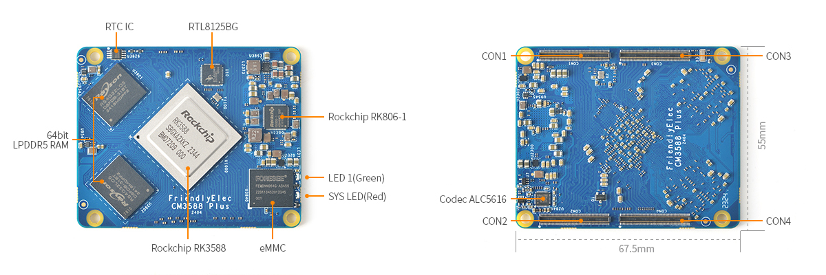
Fig 1.0: CM3588 Plus Component Mapping (RK3588, LPDDR5 RAM, eMMC, and Peripherals)
The Lascope hardware architecture is built on a Modular Sub-PCB Model. By separating the high-speed computing core from the user interface and illumination modules, we ensure:
- EMC Isolation: High-speed signals are isolated on the Main Board (Board 1).
- Serviceability: Individual modules (Buttons, LEDs, Battery) can be replaced or upgraded independently.
- Thermal Efficiency: Optimized heat dissipation paths for the RK3588 SoC.
| Board ID | Name | Role | Specs |
|---|---|---|---|
| BOARD 1 | Main Controller | System Logic & Vision | RK3588, 64-bit LPDDR5, Dual RTL8125BG |
| Board ID | Name | Role | Key Specs |
|---|---|---|---|
| BOARD 5 | Camera LED | Endoscopic Light Source | High-CRI 5700K LEDs |
| BOARD 6 | LED Controller | PWM Dimming Logic | TLC59108 I2C Driver |
| Board ID | Name | Role | Key Specs |
|---|---|---|---|
| BOARD 4 | Battery BMS | Power Management | Smart Charging & Fuel Gauge |
| BOARD 2 | Button Sub-PCB | Tactile Interface | 5-Way Navigation Switch |
| BOARD 3 | Status Panel | Visual Feedback | 5-LED Diagnostic Array |
| BOARD 7 | Power Logic | Soft-Start Circuitry | Latching Power Switch |
| Attribute | Specification |
|---|---|
| PCB Stackup | 8-Layer High-Density (Main) / 2-Layer (Sub) |
| Material | Isola 370HR / IT-180A (High TG) |
| Surface Finish | Lead-Free ENIG (Au: 0.05um, Ni: 3um) |
| Impedance | 90Ω Differential (USB), 100Ω (Ethernet) |
| Certification | IPC-A-600 Class 2 Compliance |
- Gerber Review: Open the
.zipfiles in each directory using a CAM tool (e.g., CAM350 or Gerbv). - SMT Assembly: Provide the
PickAndPlaceandBOMfiles to your PCBA partner. - Mechanical Fit: Use the provided
.stepmodels to verify enclosure clearances before milling.
Proprietary and Confidential | © 2026 Lascope Medical Imaging Systems