A compact and low-cost ECG monitoring device that captures heart signals, analyzes them using onboard AI, and detects abnormalities in real time. The system works completely offline and automatically sends emergency alerts via GSM when a critical condition is detected, making it highly useful for rural and remote healthcare applications.
This project is an ESP32-based portable medical system that can continuously monitor heart activity and automatically send emergency alerts with live GPS coordinates if an abnormality is detected. It also calculates blood pressure without a cuff and shows live ECG waveforms on an OLED screen. The goal is to create a low-cost, life-saving diagnostic prototype that is accessible for rural families and easy to carry.
This system continuously watches the user's heart rhythm using an ECG sensor and a pulse oximeter.
If a critical cardiac abnormality is detected (or the manual SOS button is pressed):
- A GSM module sends an SMS to caregivers.
- The SMS includes the patient's BPM, live GPS location, and a 5-second snapshot of ECG data.
- A 0.96" I2C OLED shows the status as "Abnormal".
If the heart rhythm is normal:
- No emergency SMS is sent.
- The OLED continuously displays the live P-Q-R-S ECG waveform, current BPM, and battery percentage.
- The system quietly monitors the user's condition.
This makes it useful as a portable, automatic emergency response system for elderly patients or individuals with known heart conditions.
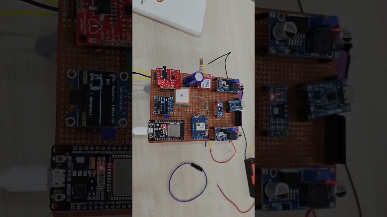
- Automatic detection of abnormal heart rates (tachycardia/bradycardia)
- Cuff-less blood pressure estimation using Pulse Transit Time (PTT)
- Automatic SMS alerts with live GPS location
- Real-time medical-grade ECG waveform display on a 0.96" OLED
- Manual tactical emergency button for immediate assistance (single/double press)
- Fully portable with a rechargeable 2000mAh Li-ion battery system
- ESP32 Devkit V4 – Main microcontroller that reads sensors, processes the AI logic, and controls communication
- AD8232 ECG Module – Captures the electrical activity of the heart
- NEO-6M GPS Module – Tracks live satellite location for emergency alerts
- SIM800L GSM Module – Sends SMS alerts over cellular networks
- 0.96" I2C OLED Display – Shows the live ECG graph, BPM, and system status
- Tactical Push Button – Used as a manual emergency trigger
- 2000mAh Li-ion Battery – Main power source
- TP4056 Charging Module – Handles safe battery charging
- LM2596 Buck Converter x2 – Regulates voltage to 5V and 4.0V rails
- 2200µF Capacitor – Stabilizes the SIM800L power supply
- 200kΩ and 100kΩ Resistors – Voltage divider for battery level monitoring
The power system uses a single Li-ion battery regulated into two separate voltage rails:
Battery (3.7V Li-ion)
    └── TP4056 (Charging & Protection)
            └── LM2596 #1 → Set to 5V
                    ├── ESP32 VIN
                    ├── GPS VCC
                    └── OLED VCC

            └── LM2596 #2 → Set to 4.0V
                    └── SIM800L VCC
                         (+ 2200µF capacitor across VCC and GND)
Important: SIM800L must have its own separate 4.0V supply from LM2596 #2. It can draw up to 2A during SMS transmission. All GND lines from every module must be connected to a common ground.
| OLED Pin | ESP32 Pin |
|---|---|
| VCC | 3.3V |
| GND | GND |
| SDA | GPIO 21 |
| SCL | GPIO 22 |
| GPS Pin | ESP32 Pin |
|---|---|
| VCC | 5V |
| GND | GND |
| TX | GPIO 16 |
| RX | GPIO 17 |
| GSM Pin | ESP32 Pin |
|---|---|
| VCC | 4.0V (from LM2596 #2) |
| GND | Common GND |
| TX | GPIO 25 |
| RX | GPIO 26 |
| AD8232 Pin | ESP32 Pin |
|---|---|
| VCC | 3.3V |
| GND | GND |
| OUTPUT | GPIO 34 |
| LO+ | GPIO 32 |
| LO- | GPIO 33 |
| RL | GND |
| Button | ESP32 Pin |
|---|---|
| One leg | GPIO 27 |
| Other leg | GND (Uses INPUT_PULLUP) |
Battery (+) → 200kΩ resistor → GPIO 35 → 100kΩ resistor → GND
- All GND connections from every module must share a common GND.
- SIM800L must be powered from its own separate 4.0V LM2596 rail — do NOT power it from ESP32's 3.3V or 5V pins.
- Place a 2200µF capacitor across SIM800L's VCC and GND to handle current spikes.
- Do NOT use GPIO 12 for any connection — it affects ESP32 boot mode.
- GPS uses Serial2: TX → GPIO 16, RX → GPIO 17.
- GSM uses Serial1: TX → GPIO 25, RX → GPIO 26.
- The ESP32 powers up and initializes the OLED, GPS, GSM, and sensors.
- The OLED displays the starting interface and battery percentage.
- In the main loop, the ESP32 continuously reads the analog output of the ECG sensor.
- If the calculated BPM is between 50 and 120 (normal range):
- GSM stays in standby → No SMS sent
- System state is set to
Normal - OLED shows the live scrolling ECG waveform and
BPM: [Value] Normal
- When the heart rate drops below 50 BPM or spikes above 120 BPM, the status changes to
Abnormal. - The ESP32 tracks this condition. If the abnormality persists for 10 continuous seconds:
- The ESP32 fetches the latest latitude and longitude from the GPS module.
- It formats an alert message including the location and the last 640 samples of ECG data.
- The GSM module sends the SMS to the predefined caregiver number.
- The OLED updates the status text to
Abnormal.
- If the user single-presses the Tactical Button, a location + vitals SMS is sent instantly.
- If the user double-presses the Tactical Button, a full Emergency Assistance SMS is broadcast.
The ESP32 code follows this algorithm:
-
Setup phase
- Initialize Serial, GSM Serial (GPIO 25/26), GPS Serial (GPIO 16/17), and I2C OLED
- Set pin modes for ECG output, LO+/LO- leads-off detection, and the tactical button
- Show initial startup screen on OLED
-
Loop phase
- Signal Read: Read the analog value from the ECG pin (GPIO 34).
- Leads-off Check: Read GPIO 32 and GPIO 33 to confirm electrode contact.
- Waveform Mapping: Apply PQRST template to map the signal into the 640-sample circular buffer.
- BPM Calculation: Measure time between R-peaks to calculate Beats Per Minute.
- Battery Read: Sample GPIO 35 via the voltage divider to calculate battery percentage.
- Display Update: Draw the GPS location text, ECG waveform, BPM, and battery on OLED.
- Threshold Check: If BPM is abnormal for more than 10 seconds, trigger
sendTacticalSMS(). - Button Check: If the button on GPIO 27 is single or double pressed, trigger the appropriate SMS function.
cardiobytes-cardiac-monitor/
├── code/
│   └── cardiobytes_main.ino
├── diagrams/
│   ├── block_diagram.png
│   ├── circuit_schematic.png
│   └── architecture_flowchart.png
├── images/
│   ├── system_setup.jpg
│   ├── sms_alert_screenshot.jpg
|   ├── Soldered ECG project prototype
|   ├── gps_locking_test
├── docs/
│   └── CARDIOBYTES_REPORT.pdf
└── README.md
- Build the hardware according to the wiring tables above. Make sure the SIM800L has adequate current supply from the dedicated LM2596 rail.
- Update the code: Open
cardiobytes_main.inoin the Arduino IDE and replace the placeholder phone number in theAT+CMGScommand with your actual emergency contact number. - Upload the sketch to your ESP32 board using Arduino IDE. Select ESP32 Dev Module from the Boards menu.
- Attach electrodes: Place the ECG electrodes on your body (Right Arm, Left Arm, Right Leg/RL to GND).
- Power on the device and wait for the OLED to display the live ECG waveform.
- Test the SOS: Press the emergency button twice quickly to verify the GSM module sends an SMS with your location.
Important: This is an educational and prototyping project. It is not a certified medical device. Always consult medical professionals for actual health diagnoses and do not rely solely on this prototype for life-threatening emergencies.
- Add a companion mobile app via Bluetooth/Wi-Fi to view historical ECG data
- Integrate advanced Machine Learning (TinyML) on the ESP32 to classify specific arrhythmias such as Atrial Fibrillation
- Design a custom PCB to reduce the overall size to fit on a wrist or chest strap
- Add an SD Card module to log heart data over 24 hours (Holter monitor style)
- Important note is that it is a hackathon modle so the power supply and the connection of the board and proper utilization of the ESP32 board was not acheived.
This project shows how biomedical sensors, an ESP32, and cellular communication can be combined to build a portable health monitoring system. It is an excellent project for learning:
- How to acquire and filter noisy analog biological signals (ECG/PPG)
- How to manage multi-module serial communication on an ESP32
- How to interface with cellular networks using AT commands via a GSM module
- How to design life-saving wearable technology with real-world applications
Anyone familiar with Arduino/ESP32 programming can reproduce and extend this project for advanced biomedical engineering and IoT applications.
All the required codes and prototype images and results obtained are all in the respective folders and files , you can get everything required to reproduce the project .